lunedì 18 gennaio 2010
mercoledì 23 dicembre 2009
Simple tone generator tutorial
I've posted a simple tone generator tutorial here. Feel free to post comments.
giovedì 12 novembre 2009
giovedì 5 novembre 2009
lunedì 2 novembre 2009
Playing with QT part one: configure your environment
I've been using WxWidgets at work for some time and I wanted to try something different for my framework, so I decided to give a try to Qt.
I had troubles finding good documentation, so here's a small guide about how to configure Qt with MSVC in a few simple steps.
First of all I assume you have a copy of MSVC 2005 (not an express versions). The problem with express versions is they don't support plugins, so the integration with express versions might not be optimal.
Are you ready? Let's go.
1- download a copy of Qt from here. Get the SDK, windows version.
2- install the sdk.
3- add the environment variable "QTDIR = installdir\version\qt". In my case I installed Qt in c:\qt and the version is 2009.04 so "QTDIR = c:\qt\2009.04\qt". To add an environment variable, right-click the computer icon on your desktop, select "properties". A window opens, select "Advanced system settings", then select "Environment variables...".
4- copy the following text "configure -no-sql-sqlite -no-qt3support -no-opengl -platform win32-msvc2005 -no-libtiff -no-dbus -no-phonon -no-phonon-backend -no-webkit", open the notepad and past it. Save as "qt-configure.bat" in "installdir\version\qt". You can play with it, but that configuration works for me. I found it somewhere and looks fine.
5- Launch MSVC. Launch "visual studio command prompt" from tools menu. A visual studio command prompt includes MSVC environment variables. The other solution is to manually open a command prompt (start button->execute->cmd.exe) and launch vcvars32.bat in your MSVC install dir (under vc\bin).
6- type "cd installdrive\installdir\version\qt". In my case "cd c:\qt\2009.04\qt".
7- execute our .bat file by writing "qt-configure" or "qt-configure.bat". Wait until Qt generates all makefiles for MSVC.
8- Launch the compilation with nmake. Type "nmake".
9- Wait until the compilation is completed. It's going to take a lot of time.
10- Close the command prompt and MSVC, download the add-in and install it. At this time the last version is 1.1.1
11- Reboot and start MSVC, go to qt menu->qt options. Add a new version, in my case the path is c:\qt\2009.04\qt.
Now you can use Qt with MSVC. You can create Qt applications and Qt designer plugins easily.
Problems I have encountered so far are:
- After installing the plugin, everytime you execute or compile, MSVC will open the entire solution tree and scroll down until the end of the tree. I hope they'll fix it soon.
- The Qt designer plugin appwizard generates code that needs a small modification to be correctly loaded by the designer. I'll discuss this problem in another post.
I'm using Windows Vista 32-bit and everything works.
martedì 20 ottobre 2009
Be linear or be wrong: get rid of gamma correction!
This is a recurring topic.
Everything you need to know about gamma correction and linear color spaces is available for free, in GPU Gems 3, here.
When I received my copy of GPU Gems 3 it took a while to correctly understand what they were talking about in chapter 24. Call me dumb, but I think that chapter is a complex description of a simple problem.
I don't pretend to do better, but here's a simple description of the problem (toghether with a solution). I won't cover sRGB textures or mipmap generation.
It's nothing but a very simple post. After all many people just get textures as standard images, ask the rendering API to generate mipmaps for them and draw stuff on screen.
The problem
The human eye is more sensitive to dark colors and the precision of a display is limited to 256 shades (8-bits) per color channel. In order to increase the amount of shades we can distinguish on a monitor/lcd panel, a function is applied by the display. This operation is called "gamma correction", and is typically c=x^y, where x = original shade, y = something between 2.0 and 2.4 and c is the perceived color.
For simplicity, I will assume a gamma correction factor of 2, thus y = 2.0.
It is important to understand your display is doing something RIGHT NOW to make images look "better". The web page you're looking at is corrected by your display according to what your eyes sees better.
So?
The problem is in theory an intensity should scale linearly. If 1.0 is full intensity, then 0.5 should result in half the intensity. When we apply gamma correction we have:
1.0*1.0 = 1.0 -> full intensity (correct)
0.5*0.5 = 0.25 -> 1/4 intensity (wrong)
Thus, a gamma corrected color space is not linear.
How things can get wrong: an example
Alice the graphic artist has to pick up a solid grey color that can fit well with a white background. She creates a new white image, then draws a solid gray rectangle. She changes the rectangle color until she finds a good one. She picks that color and saves a 1x1 image.
Bob the programmer receives the 1x1 image to be applied as a texture to an interface button.
Alice is happy, she thinks that dark grey, of approximately 1/4th the intensity of full white, is going to fit well.
Bob is happy, he got a 1x1 image and all he needs to do is to load that texture and draw the button.
They are wrong.
The color received by Bob IS NOT THE SAME COLOR Alice saw on her display.
Alice had the perception of a color whose intensity is (0.25,0.25,0.25), since she saw something gamma corrected. The color saved in the image is actually (0.5,0.5,0.5)!
Bob draws the control... and the color is fine.
Bob and Alice think the problem is solved, actually they never thought it was a problem to display a color, but they don't know there's a subtle mistake in their image rendering process.
Why did Bob see the correct color?
Bob loads the texture (0.5,0.5,0.5), then renders the button background color. The display applies gamma correction so:
0.5*0.5 = 0.25
This is the same color Alice saw on her display.
How can things go wrong?
Bob is asked to apply a simple diffuse lighting model to the interface, so he goes for the standard dot(N,L).
Now, let's do the math. We assume dot(N,L) for a given pixel is 0.8.
We have 0.5*0.8 = 0.4
Then the display applies gamma correction:
0.4 * 0.4 = 0.16
We are multiplying the original color by 0.8. That means we want 80% of the original intensity.
Alice saw a color intensity of 1/4th (approx 0.25) on her screen, so we should get a color intensity of 0.20. But we have 0.16 instead of 0.20!
Obviously there's a mistake, as the output color is darker than the one we expected. It's an huge error, 20% darker than we expected!
What's the problem?
Problem number one: the original color isn't the one Alice saw on her display.
Problem number two: the display remaps our color in a non linear color space.
Which is the solution?
The solution is simple and is divided into two steps. Let's see the first.
The original color is not gamma corrected, as its intensity is 0.5. We need to work on the same color intensity Alice saw on her display.
So the first step after the texture sampling is to apply gamma correction:
0.5*0.5 = 0.25
Now we are working on the proper color shade.
0.25*0.8 = 0.2
This is the color we expect to see.
Bob tries to render the interface and he gets something very dark. Too much dark.
Bob forgot the display applies gamma correction AGAIN, so:
0.2*0.2 = 0.04
Thus the second step required is to cancel out the gamma correction, by applying the inverse operation, just before returning the color in our pixel shader.
0.2^0.5 = 0.4472
The display will gamma-correct 0.4472, so:
0.4472*0.4472 = 0.19998
Except for limited precision, Bob is now seeing the correct color shade.
In brief, the solution is the following:
- get the color
- apply gamma correction
- perform operations
- apply inverse gamma correction
- output to screen (this will cancel out the previous step)
Note the same also applies to constants like the color of a light.
It's easy to understand all those mistakes lead to wrong rendering output, expecially when dealing with multiple lights.
Be careful
Just a couple of hints.
Unless you are storing intermediate data on a buffer with 16-bit per channel, NEVER store gamma corrected colors in buffers, or you'll get horrible banding. The problem is by applying gamma correction to a color, you require more precision than the one available on a 8-bit channe. Let's do the math:
1.0/255.0 = 0.003921
This is the step between each intensity for an 8-bit channel. You can't be more precise than that.
"color as an 8-bit value in the image" vs "float you get in your pixel shader"
0 = 0.0
1 = 0.003921
2 = 0.003921+0.003921
.....
254 = 1.0f-0.003921
255 = 1.0
If you apply gamma correction and store the results in an 8-bit per channel buffer you can calculate which is the minimum color you can represent.
0.003921^0.5 = 0.06261
No color below 0.06261 can be represented.
Which color is 0.06261 in your image?
0.06261*255.0 = 15,96.
That means all colors between 0 and 15 will become 0 in your intermediate 8-bit buffer, if the float-to-int conversion is truncation. If it's done by rounding to the nearest integer, then all colors between 0-7 will become 0 while the ones between 8-15 will be 1. Either way, it's not good.
You may ask: what does happen to colors greater than 15?
The same principle applies.
Your image (8-bit numbers) has a color X and a color X+1.
Your shader interprets them as x/255.0 and x/255.0 + 0.0039. When you apply gamma, the difference between the two colors gets so small there's no way to distinguish them.
When you save your color you have lost information, thus the result is an awful rendering with color bands when you retrieve it.
The lesson is: IF THE INTERMEDIATE BUFFER HAS 8-BIT PER CHANNEL, ALWAYS STORE THE GAMMA UNCORRECTED (ORIGINAL) DATA.
Another solution is to use sRGB textures, have a look at the GPU Gems 3 chapter for that.
Which shader instructions should I use?
It's simple, assuming a 2.0 gamma.
Apply gamma correction:
col = col*col;
Cancel display gamma correction:
col = sqrt(col);
Assuming a 2.2 gamma things are a bit different
Apply gamma correction:
col = pow(col,2.2f);
Cancel display gamma correction:
col = pow(col,1.0f/2.2f);
Note: if you're using alpha testing or alpha blending then save the alpha channel value to a temporary variable before applying the color space transformations then restore it. Alpha channel in the original image is ok. Normal maps and height data are also ok.
How does a correct linear rendering looks like?
Sorry for the bad quality, here's a simple sphere with a single spot light.
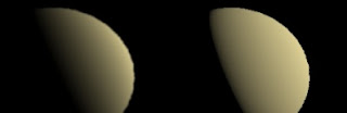
Left: wrong rendering. Right: correct rendering.
They look different than the ones on GPU Gems 3 because the ambient term is zero.
domenica 18 ottobre 2009
Working with D3D10: fullscreen quads inside.
As I already pointed out, the framework has D3D9 and D3D10 support.
The D3D10 Rendering Subsystem has been implemented from scratch this summer in two sessions, 4-5 hours each. While I have been working with D3D9 for a long time, that was the first (and until today, the only) time I wrote D3D10 code.
Here's the story in brief.
I had a running D3D9 rendering subsystem class, derived from a base class. I decided to give a try to D3D10, so I looked around for hints and tutorials.
I started with DirectX10 documentation and this. IMHO tutorials often aren't the best way to learn something (expecially when it comes down to properly detect errors, allocate/release resources, cleverly store objects, etc.), but they are great if you use them as reference (working) code.
I adapted my D3D10 code so that it could fit the rendering subsystem requirements, keeping YAGNI in mind.
The next day I had almost everything I needed already working. Shaders, textures (materials), shader parameters, vertex and index buffers, render targets. The reference sample code at that time was simple but feature rich: a 3d quad with a texture coloured and zoomed with shader parameters rendered to a render target, that is used as texture for the same quad rendered in another (rendering) pass.
Now, three months later, I'm working on the D3D10 rendering subsystem again.
What's good about it is since then I had to add very little functionalities in my D3D10 rendering subsystem. Despite my little knowledge and the fact I don't take advantage of useful features like constant buffers, the subsystem is fast.
What's bad is I "discovered" today something very important is missing: rendering a full-screen quad. Hey, after all that's what YAGNI is about: I need it now, so I'm going to implement it.
The rendering subsystem provides the user the chance to draw a rectangle, via this method:
NxBool DrawRect( NxFloat i_fX0, NxFloat i_fY0, NxFloat i_fX1, NxFloat i_fY1 ) = 0;
In D3D9 the implementation is straightforward, I have a local array with per-vertex data initialized according to the parameters submitted, I set a proper vertex format with position and UVs and I use DrawPrimitiveUP.
In D3D10, without such a mechanism, there are two options:
- use a common VB/IB pair and apply a proper transformation
- don't use buffers at all
As for the second solution, DirectX documentation covers this subject.
I decided to write something like that, here are a few hints:
1- don't use a triangle list, use a triangle strip (4 vertices instead of 6). Be careful with the vertex order. When I have to render an ABCD quad (A=(0,0) B=(0,1) C=(1,1) D=(0,1))*, the order I'm using is "BCAD". The reason is since the strip is built from the last two vertices of the first primitive, they need to be the vertices of the shared edge.
2- I didn't give a try to this idea, but if you need a simple fullscreen quad you could try rendering a single triangle of size ((0,0) (2,0) (0,2))* and scale your vertex data by a factor of two. Clipping should avoid extra calculations and in theory you'll get your good ol' fullscreen quad. Since this solution doesn't work with rects, I didn't implement this idea.
What's great is I don't have to worry about pixel-texel centers alignment. If you don't know what I'm talking about and you are using D3D9 you definitely need to have a look here before starting develop any postprocessing shader.
When using the framework, the main difference between D3D9 and D3D10 implementations is the amount of constraints in postprocessing shader. In D3D9 user has to write a simple passthrough vertex shader and provide two variables, one for half pixel width and another one for half pixel height. In D3D10, the vertex shader is more complex and the required parameters are the quad coordinates X0,Y0 X1,Y1.
The next step has been to create a specific class for screen rects. I wanted to be able to push screen rects inside a scene, so that building interfaces or postprocessors should be easy.
When testing compatibility I tried multithreaded and singlethreaded pipelines, they worked. I decided to check my D3D9 rendering subsystem and nothing is shown on screen.
It seems the subsystem doesn't correctly expose shader parameters. Yes, I haven't implemented it yet because of YAGNI!
Now I know what I'm going to implement today... ;)
* To make the post easier to understand I'm assuming the reference coordinate system is (0,0) at the top left corner and (1,1) at the bottom right. Which of course is NOT the case of D3D.
Iscriviti a:
Post (Atom)